

How to Specify Slot Positions on a Cylindrical Metal Part
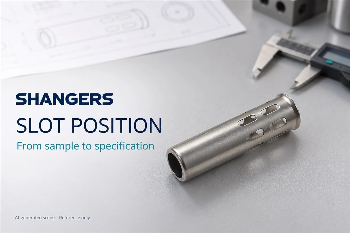
"Four slots near the end" may describe a photograph, but it leaves several questions unanswered for a quotation. Which end is the reference? Does the position refer to the slot centre or its nearest edge? Are the openings equally spaced around the body? A clearer enquiry separates slot size from slot location.
1. Name the end you are measuring from
Choose an identifiable end face or other drawing reference. If one end has a rim, state whether measurements start at the outer end face, the rim shoulder or another surface. Use the same reference consistently in the drawing and enquiry notes. For an existing engineering drawing, retain its specified datum scheme rather than adding a conflicting one.
2. Separate size from axial position
Give the slot length and width, then locate it along the body. A centre position and an edge distance are different descriptions: label which one you mean. Show the slot-end shape as well. If you use a dimensioned sketch, make sure the supplier can distinguish the feature dimensions from its distance to the reference end.
3. Show the arrangement around the cylinder
A side photograph can hide openings on the far surface. An end view or clearly labelled additional view can communicate the number of rows and their angular relationship. If the openings are equally spaced, say so; if they are not, provide the individual positions. Do not let a partly hidden photograph stand in for the complete pattern.
4. Identify any feature that fixes the rotational position
If an opening must align with a notch, flat or mating feature, show the relationship on the drawing. If the part has no required rotational relationship, state that too. This helps the supplier distinguish a functional alignment requirement from an incidental orientation in a photograph.
5. Describe the finished edges
Explain whether slot edges contact another component, remain accessible during handling or have an appearance requirement. Specify the required edge condition and acceptance criteria rather than using an undefined phrase such as "perfectly smooth." Where a finish is requested, clarify whether the critical dimensions apply before or after that finish.
A compact enquiry checklist
- Body drawing with diameter and length requirements.
- Named reference end and clearly labelled slot location.
- Slot count, length, width and end shape.
- End view showing the complete circumferential pattern.
- Any alignment requirement to another feature.
- Material, edge and finish requirements, drawing revision and quantity.
For a part supplied only as a sample
Photograph both ends and enough side views to show all openings. Mark the reference end in the pictures and supply measured values where possible. Ask the supplier which remaining details need a drawing or physical sample. A photo-based estimate should not be mistaken for approval of a complete manufacturing specification.
SHANGERS accepts enquiries based on drawings or reference samples. Send your component details to discuss the next step, or browse our metal stamping parts.


